BATTERY SAFETY & TECHNOLOGY
When a battery energy storage system (BESS) starts up, connecting the battery to an inverter or power conversion system may create a sudden surge of current.
This is known as inrush current. If it is not properly controlled, it can place significant stress on contactors, capacitors and other electrical components.
A precharge resistor is a small but important component that helps manage this process, supporting smoother and more controlled system startup.
1. What Is a Precharge Resistor?
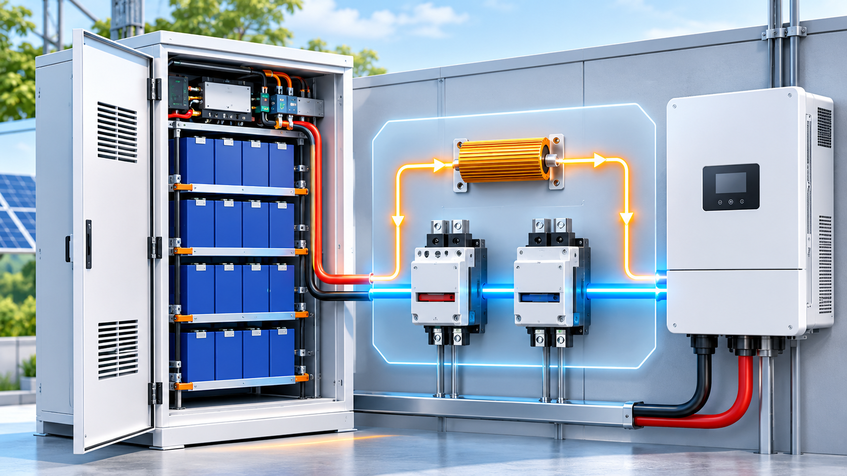
A precharge resistor is a current-limiting component used in the precharge circuit of certain battery energy storage systems.
In systems with large DC-link capacitors, connecting the battery directly to an initially uncharged capacitor bank can produce high inrush current.
A properly designed precharge circuit allows the capacitors to charge through a controlled current path before the main contactor completes the connection.
This helps reduce electrical stress during startup.
Why Is Precharging Important?
Without appropriate inrush current control, startup may cause:
- Contactor damage: High current can contribute to contact wear or contact welding.
- Component stress: Capacitors, connectors and other components may experience excessive electrical stress.
- Protection trips: Sudden current surges may trigger protective devices.
- Startup failures: The system may fail to complete its intended startup sequence.
Precharging helps reduce these risks, although it does not replace other electrical protection measures.
2. How Does a Precharge Circuit Work?
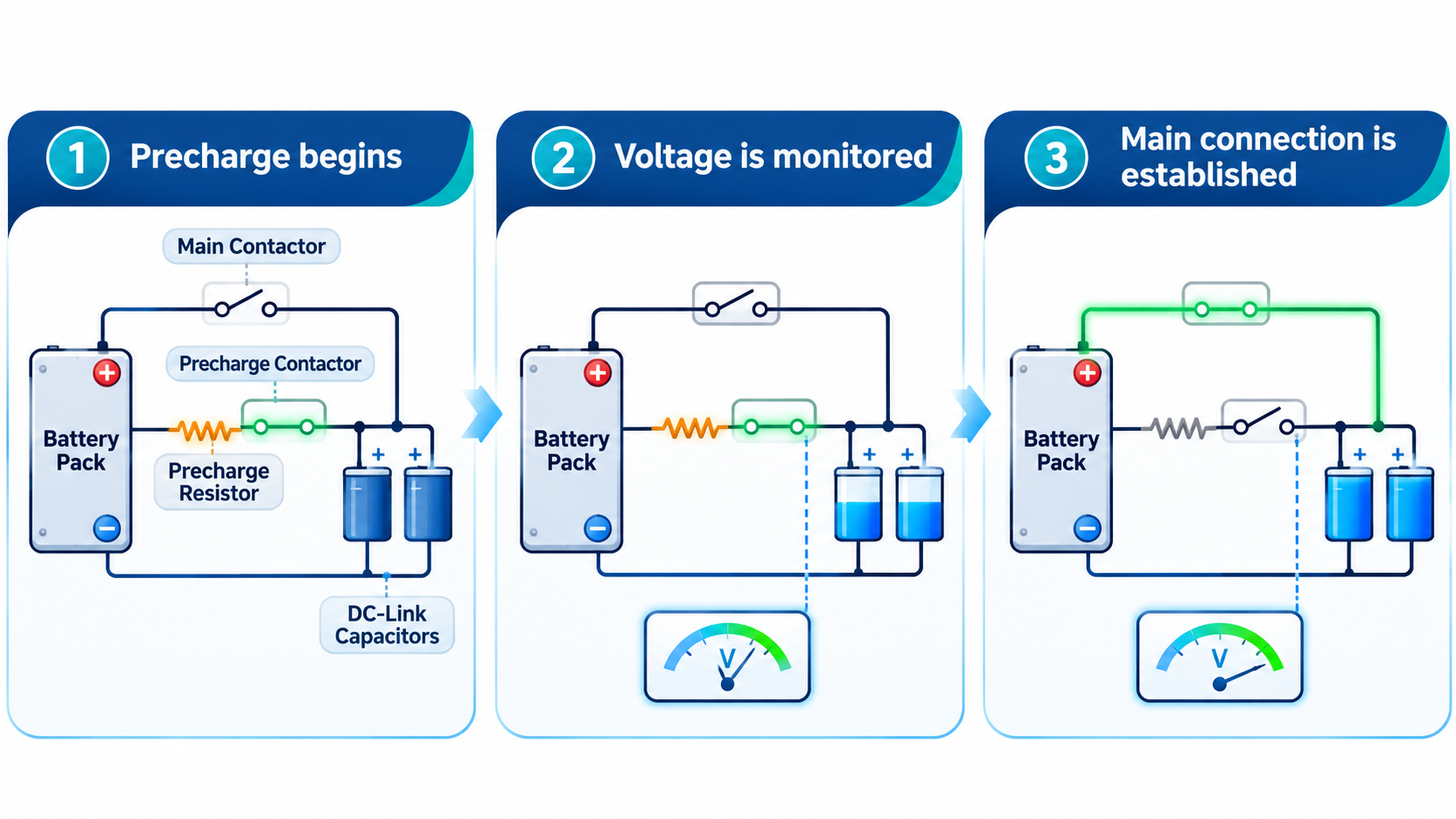
In a typical contactor-based battery system, precharging occurs before the main power path is fully established.
Step 1 — Precharge begins
A controlled current path through the precharge resistor begins charging the DC-link capacitors.
Step 2 — Voltage is monitored
The control system checks whether the DC bus reaches the required condition within the specified time.
Step 3 — Main connection is established
Once the required conditions are satisfied, the main contactor can close and bypass the precharge path.
This is a conceptual explanation, not an installation or wiring diagram. Actual sequences depend on system architecture.
The required voltage difference, timing and control logic vary by equipment design. They must follow the applicable manufacturer's specifications.
3. What Happens When Precharging Fails?
Precharge circuits can experience several types of faults.
| Potential issue | Possible consequence |
|---|---|
| Open-circuit resistor | Capacitors may fail to precharge |
| Incorrect or degraded resistor | Abnormal charging time or excessive component stress |
| Contactor malfunction | Precharge or main connection may not operate as intended |
| Voltage sensing fault | Incorrect assessment of precharge completion |
| Control system fault | Startup may be interrupted or improperly sequenced |
A properly designed system should detect relevant failures and respond according to its validated protection strategy.
Repeated precharge faults should be investigated by qualified personnel rather than bypassing the protection circuit.
4. Is a Precharge Resistor the Same as a BMS?
No. They perform different functions.
A Battery Management System (BMS) monitors and manages specified battery operating conditions, which may include cell voltages, temperatures and current.
A precharge resistor limits current in a designated startup circuit.
In some systems, the BMS or another controller coordinates the precharge sequence, but the resistor itself does not monitor battery health or make protection decisions.
Both functions must be considered within the complete battery-system design.
5. What Should B2B Buyers Consider?
For battery manufacturers and energy storage integrators, precharge design is an important part of evaluating a complete battery system.
Before purchasing components or selecting an integrated solution, buyers should confirm:
- Whether the system requires a precharge circuit.
- Which controller manages the startup sequence.
- Compatibility with the intended inverter or power conversion system.
- Relevant component ratings and manufacturer documentation.
- How precharge failures are detected and handled.
Not every LiFePO4 battery product uses the same precharge architecture. Component selection and validation must be based on the actual system design.
Reliable Startup Begins with Proper System Design
Precharge resistors help manage inrush current during startup, reducing stress on electrical components in appropriately designed battery energy storage systems.
However, reliable operation depends on the coordination of battery management, switching devices, electrical protection and system controls.
Universal Through supplies LiFePO4 battery cells, BMS products and energy storage components for B2B sourcing and OEM/ODM projects.
Contact Our Team to discuss your energy storage component requirements.Post time: Nov-03-2026